In the complex world of system design and software development, clarity is king. You could spend hours describing an application's architecture or a business process in words, only for nuances to get lost in translation. Or, you could simply show it. That's where Understanding UML Diagram Types and Uses becomes indispensable. The Unified Modeling Language (UML) isn't just a technical tool; it's a universal visual language that helps you communicate intricate ideas with precision, bridging the gap between abstract concepts and concrete implementations.
Think of UML diagrams as the blueprints for your digital creations, whether you're sketching out a new software feature, mapping a complex financial transaction system, or designing an entire enterprise architecture. They bring order to chaos, transforming complex ideas into clear, digestible visuals that everyone, from developers to stakeholders, can understand.
At a Glance: Your Quick Guide to UML Diagrams
- UML is a visual language: It provides a structured way to represent system components and their interactions.
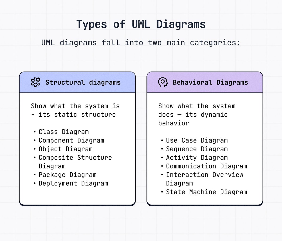
- 14 diagram types exist: Categorized into two main groups: structural (what the system is) and behavioral (what the system does).
- Structural diagrams show static architecture: Elements, structure, and connections (e.g., Class, Component, Deployment).
- Behavioral diagrams show dynamic aspects: How components interact and change state (e.g., Use Case, Activity, Sequence).
- Key benefits: Improved design clarity, enhanced communication, early gap identification, efficient teamwork, faster decision-making.
- Creating them: Define purpose, identify elements, establish relationships, refine, and review.
- Best practices: Keep it simple, consistent, and logical; avoid overcomplication.
Why Visual Blueprints Matter: The Power of UML
Before diving into the specifics, let's nail down why we even bother with UML. Imagine trying to build a skyscraper without architectural drawings. You'd likely end up with a mess of misaligned floors, incompatible components, and constant rework. Software and system development are no different. They demand a clear, shared vision.
UML diagrams serve as that shared vision, acting as a common visual language for architects, developers, business analysts, and project managers alike. They demystify complexity, allowing teams to:
- Clarify Design: Quickly see the structure of an application, how different modules fit together, or the flow of a critical business process. This helps in understanding the system's construction, maintenance needs, and how it might scale in the future.
- Enhance Communication: Move beyond ambiguous prose. Visuals provide a concrete reference point for discussions, ensuring everyone is on the same page. This is especially vital in distributed teams or when onboarding new members.
- Streamline Development: Identify potential flaws, inconsistencies, or missing pieces early in the design phase, long before a single line of code is written. Catching issues here is far cheaper and easier than fixing them during testing or after deployment.
- Boost Collaboration: Facilitate more effective brainstorming and problem-solving sessions. When ideas are visually represented, teams can iterate faster and make informed decisions more efficiently.
Ultimately, UML isn't about rigid adherence to notation for its own sake; it's about making your life easier by making complex systems understandable.
The Two Pillars of UML: Structural vs. Behavioral Diagrams
UML organizes its 14 diagram types into two fundamental categories. Understanding this distinction is key to choosing the right diagram for your specific modeling challenge.
1. Structural Diagrams: What Your System Is
Structural diagrams are like anatomical charts of your system. They represent the static architecture, showing the elements, their internal structure, and how they connect. If you want to understand the system's "anatomy" – its components, their organization, and relationships – you'll turn to these diagrams. They're invaluable for designing the underlying framework, anticipating maintenance challenges, and planning for future growth.
Let's explore the key types:
Class Diagram: The Heart of Object-Oriented Design
If you've heard of UML, you've almost certainly heard of the Class Diagram. It's the cornerstone of object-oriented solutions, illustrating classes, their attributes (data), their operations/methods (behaviors), and the various relationships between them (e.g., inheritance, association, aggregation, composition).
Each class typically has three sections: its name, its attributes, and its operations. This diagram is crucial for laying out the logical structure of a system, defining the building blocks, and understanding how they interact at a conceptual level. When you're creating effective Class Diagrams, you're essentially mapping out the blueprint of your software's domain model.
Component Diagram: Assembling the Software Puzzle
When you need to visualize the structural relationships between different software components within a larger system, the Component Diagram is your go-to. Components are self-contained, replaceable parts of a system that encapsulate their contents and provide interfaces to interact with other components.
This diagram helps you understand the high-level architecture, how different modules (like a database component, a UI component, or a logging service) are linked, and what interfaces they use to communicate. It's particularly useful for complex, distributed systems where different parts might be developed by separate teams.
Deployment Diagram: Hardware Meets Software
Ever wondered how your software actually runs on physical hardware? The Deployment Diagram answers that. It illustrates the physical deployment of artifacts (like executables, libraries, and configuration files) on specific nodes (hardware devices or execution environments).
This diagram is essential for understanding solutions that span multiple machines, data centers, or cloud instances with unique configurations. It shows where different parts of your system reside, how they're connected (e.g., via network), and which software pieces are deployed onto which hardware.
Object Diagram: A Snapshot in Time
An Object Diagram is essentially an instance of a Class Diagram, showing the system's state at a particular moment. Instead of generic classes, it features real-world objects with specific data values. For example, where a Class Diagram might have a "User" class, an Object Diagram would show "User: John Doe" with username = "johndoe" and email = "john@example.com".
It's excellent for explaining complex relationships with concrete data examples and for verifying the correctness of your Class Diagram by demonstrating how objects would interact in a specific scenario.
Package Diagram: Organizing Your System's Logic
As systems grow, managing their complexity becomes a challenge. Package Diagrams help by showing dependencies between different packages or namespaces within a system. Packages are used to group related classes, components, or other diagrams into logical units, reducing visual clutter and improving modularity.
This diagram provides a high-level view of how different functional areas or logical layers of your system are structured and how changes in one package might affect others.
Composite Structure Diagram: Peering Inside a Class
Sometimes, a class isn't just a simple box; it has its own intricate internal structure, composed of smaller parts or "roles." The Composite Structure Diagram allows you to dive inside a class and model its internal architecture in detail. It shows how its parts are wired together to perform the class's overall behavior. This is particularly useful for modeling complex patterns or components that aggregate other components.
Profile Diagram: Extending UML (Rarely Used)
Introduced in UML 2, the Profile Diagram is a specialized structural diagram used to define custom extensions to UML itself. It's for creating "profiles" that adapt UML for specific domains or platforms by introducing new stereotypes, tag definitions, and constraints. Unless you're deeply involved in meta-modeling or extending UML, you'll likely never use this one.
2. Behavioral Diagrams: What Your System Does
Behavioral diagrams, in contrast, describe the dynamic aspects of a system. They focus on how components interact, how data flows, how states change, and how the system responds to events over time. These are your go-to diagrams for modeling system logic, user interactions, process workflows, and the overall "action" of your system.
Let's unpack the key types:
Use Case Diagram: Who Does What?
Often the first diagram you'll create, a Use Case Diagram provides a high-level graphic overview of actors (users or external systems), the functions they need (use cases), and how these functions interact within a system. It answers the fundamental question: "Who uses the system for what purpose?"
This diagram is an excellent starting point for project discussions, requirements gathering, and ensuring that your system addresses the primary needs of its users. It helps to define the scope of the system from a user's perspective, making it invaluable for optimizing Use Case Diagrams for clarity and impact.
Activity Diagram: Mapping Workflows
If you need to represent a business process or an operational workflow graphically, the Activity Diagram is your tool. It's essentially a sophisticated flowchart that describes the sequence of actions, decisions, and parallel activities involved in performing a specific task or operation.
Activity diagrams are incredibly versatile and can model everything from a simple login process to complex financial transactions. They can also serve as an alternative to State Machine Diagrams for certain scenarios, particularly when the focus is on process flow rather than object states. You might even use it to illustrate decision trees or data transformation pipelines.
State Machine Diagram: The Lifecycle of an Object
Objects aren't static; they change over time. A State Machine Diagram (also known as a State Diagram or State Chart Diagram) describes the behavior of an object or an entire system by showing its possible states and the transitions between those states in response to events.
Think of a traffic light: it can be Red, Yellow, or Green, transitioning between these states based on a timer. This diagram is crucial for modeling objects that act differently according to their current state, ensuring all possible states and transitions are accounted for and handled correctly.
Sequence Diagram: The Dance of Objects
When you want to show how objects interact over time to perform a specific scenario, the Sequence Diagram is your best friend. It illustrates the order of messages passed between objects, with time flowing vertically down the page and objects arranged horizontally at the top.
Each object has a "lifeline" showing its existence over time, and interactions are represented as arrows carrying messages. This diagram is excellent for detailing the logic of a particular use case, helping you visualize the call flow and identify potential bottlenecks or missing interactions. If you're exploring Sequence Diagrams, you're getting into the nitty-gritty of how operations unfold.
Communication Diagram: Who Talks to Whom?
Similar to a Sequence Diagram, a Communication Diagram (formerly called a Collaboration Diagram in UML 1) also focuses on messages passed between objects. However, its primary emphasis is on the structural organization of the objects and their relationships, rather than the explicit timing of messages.
Objects are arranged freely, and numbered messages indicate the sequence of interactions. It's better for understanding which objects communicate and what messages they exchange, especially when the spatial relationship between objects is important.
Interaction Overview Diagram: A High-Level Storyboard
Imagine an Activity Diagram where each "activity" is actually an entire Interaction Diagram (like a Sequence or Communication Diagram). That's essentially what an Interaction Overview Diagram is. It provides a high-level view of how multiple interaction diagrams are sequenced together to represent a larger process.
This diagram acts as a collection of interaction diagrams and their order, giving you a storyboard-like overview of complex interactions that span several distinct scenarios.
Timing Diagram: Precision in Time
The Timing Diagram is a specialized form of Interaction Diagram that focuses on precise timing constraints and the behavior of objects within a specific time frame. It's particularly useful in real-time systems or performance-critical applications where the exact duration and sequence of events matter.
Similar to a Sequence Diagram, it shows interactions between multiple objects, but it explicitly visualizes changes in state or value of an object lifeline over a linear time axis, highlighting events that trigger state changes.
Where UML Shines: Real-World Applications
UML diagrams aren't confined to a single industry or role. Their versatility makes them powerful across various domains:
- Software Development: This is UML's natural habitat. It's used to structure applications, plan architectures, design databases, and visualize algorithms. From high-level architectural designs to detailed class implementations, UML guides the entire development lifecycle.
- Business Process Modeling: Beyond code, UML can map out intricate business workflows, decision trees, and operational procedures. Activity Diagrams, in particular, are excellent for UML for business analysis, helping organizations optimize processes, identify bottlenecks, and improve efficiency.
- Project Planning & Management: Use cases can define project scope, while activity diagrams can outline task flows and dependencies. This helps project managers visualize timelines, allocate resources, and communicate progress.
- Healthcare & Finance: Industries with complex data management and transaction processing systems heavily leverage UML. Think of modeling patient data flows in healthcare or transaction processing in finance to ensure accuracy, compliance, and security.
Crafting Effective UML Diagrams: A Step-by-Step Guide
Creating a clear and useful UML diagram isn't just about knowing the notation; it's about following a structured approach.
1. Define Your Purpose: Why Are You Drawing This?
Before you even touch a tool, ask yourself: What specific problem am I trying to solve? What information do I need to convey? Is it system structure, user interaction, a process flow, or object behavior? Brainstorming the diagram's objective is the most crucial first step. A clear purpose will guide your choice of diagram type and the level of detail.
2. Identify Key Elements: Sketch the Core
Once your purpose is clear, start rough-sketching the main components. For a Class Diagram, list your core classes. For a Use Case Diagram, identify your actors and main functions. Don't worry about perfection; focus on capturing the essential entities relevant to your purpose.
3. Establish Relationships: Connect the Dots
Systems aren't just isolated components; they interact. Define how your identified elements relate to each other. Are they associated? Do they inherit properties? Do they send messages? These relationships are what bring your diagram to life and illustrate the system's dynamics. Refine these through discussions with your team or stakeholders.
4. Refine and Review: Polish for Clarity
Once you have a draft, review it critically. Is it accurate? Is it easy to understand? Are there any ambiguities? Adjust details as needed, ensuring consistent notation and logical organization. Get feedback from others – a fresh pair of eyes can spot issues you missed. Remember, the goal is clarity, not artistic prowess.
5. Choose the Right Tool: Your Digital Canvas
While paper and pencil are great for initial sketches, a dedicated UML diagramming tool makes refinement, sharing, and version control much easier. Many options exist, from online cloud-based platforms to desktop applications. The best tool for you will depend on your team's collaboration needs, budget, and specific diagramming requirements. When you need to quickly generate UML diagrams from code or text, specialized generators can significantly speed up the process.
The Dos and Don'ts of UML Diagramming
To ensure your UML diagrams truly serve their purpose, keep these best practices and common pitfalls in mind:
Do: Best Practices for Impact
- Keep it Simple: Focus on conveying one specific idea or aspect per diagram. Overloading a diagram with too much information makes it unreadable. Break down complex systems into multiple, interconnected diagrams.
- Use Consistent Notation: Stick to standard UML notation, but also be consistent within your project or organization for any chosen conventions (e.g., color-coding, naming conventions). This ensures everyone can interpret your diagrams correctly.
- Organize Components Logically: Arrange elements in a way that reflects natural flow or hierarchy. Use clear labels and avoid crisscrossing lines unnecessarily. A well-laid-out diagram is intuitive.
- Add Notes and Constraints: Use comments or OCL (Object Constraint Language) if necessary to clarify complex logic or specific rules that can't be fully expressed graphically.
Don't: Pitfalls to Avoid
- Overcomplicate Diagrams: Resist the urge to include every single detail. UML is about abstraction; too much detail can obscure the main point and render the diagram useless.
- Use Incorrect Relationships: Understand the nuances between different relationship types (e.g., aggregation vs. composition, generalization vs. realization). Misusing them can lead to incorrect system understanding.
- Inconsistent Notation: Arbitrarily changing symbols or line styles within or across diagrams will confuse your audience and undermine trust in your model.
- Poor Layouts: Diagrams that are sprawling, unorganized, or have many overlapping lines are frustrating to read and fail to communicate effectively. Take the time to arrange elements neatly.
Beyond the Diagram: Fostering Collaboration and Innovation
Ultimately, Understanding UML Diagram Types and Uses is about more than just drawing boxes and arrows. It's about fostering a culture of clarity, collaboration, and precision in system design. By providing a common visual language, UML diagrams empower teams to:
- Communicate with Precision: Minimize misunderstandings between technical and non-technical stakeholders.
- Accelerate Idea Generation: Rapidly prototype and visualize different design options.
- Improve Decision-Making: Make informed choices based on a clear understanding of system structure and behavior.
- Reduce Errors: Identify and rectify design flaws before they become costly bugs.
- Support Maintenance & Evolution: Provide comprehensive documentation that makes future changes and extensions far easier.
Whether you're sketching your next big software idea, mapping a critical business process, or just trying to get everyone on the same page, the diverse range of UML diagrams offers a powerful toolkit. Pick the right diagram for the job, keep it simple, and watch as your complex ideas transform into clear, actionable blueprints for success. The journey from concept to reality becomes much smoother when you have a well-drawn map.